|
|
|
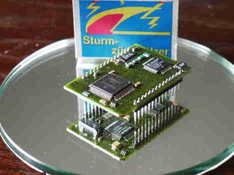
Micro-ARINC429 Decoder Flight tests of modern Avionic Systems often require data, which are only available as ARINC429 Signals, to drive analog instruments or recording. The Micro-ARINC 429 Decoder module is a small tool to solve this requirement. Following features are implemented:
Two ARINC429 Bus signals having both the standard bit rate of 100 k bit or 12,5 k bit One RS232 interface to load the parameter for the data selection and to load the Micro-Controller program.
Eight analog output voltages, produced by 13 Bit Digital-Analog-Converter in a range of +/- 4,096 Volt (1 mV/Bit) . This output voltages can represent any ARINC data with choosable Label and scaling. Selection parameter are: Input channel, Label, data mask, scaling, bias, coding BNR, unsigned BNR, BCD, Bit, SDI, SSM.
The Micro ARINC 429 Decoder has a size of 52 X 37 X 9 mm. Connection to a mother board is made via two 14 pin connectors at the edge of the device.
For supply 5 Volt, with less than. 80 mW power consumption is required. The selection of the output data is done by a Micro-Controller. Program is stored in a 32 K Byte Flash memory, 1 k Byte RAM is used for variables and an EEPROM is used to store all the section parameter. All interface logic to the ARINC Decoder IC and to the 8 DAC's is placed in a Logic Cell Array (LCA) .
To configure the Micro ARINC Decoder a special program running on a PC is used. (Operating System >= Windows98 or NT4). With this program all parameter which are used to calculate the output values can be inserted. The program then transfers them into the coding used by the Micro-Controller. Over the serial RS232 connection these parameter are then transferred to the Micro ARINC Decoder. They are then stored in the EEPROM and are permanent available for the Micro Decoder |
| [Home] [Products] |